Introduction
Robotics is one of the most exciting fields for makers and engineering students, and building an autonomous mobile robot is the ultimate rite of passage. Among beginner-friendly projects, the Arduino Object Following Car stands out as an engaging and practical build.
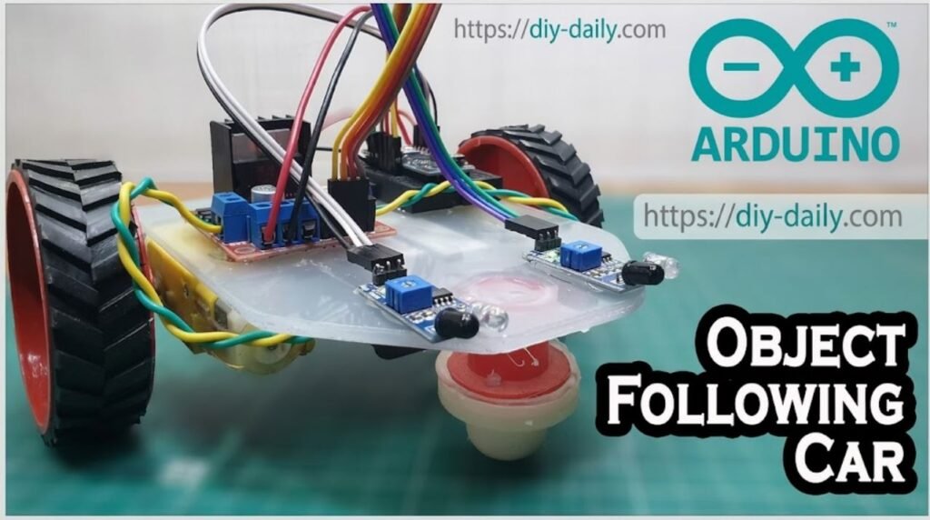
Using infrared (IR) obstacle sensors or ultrasonic modules, this smart robot detects objects placed in front of it and commands its motors to move forward, reverse, or turn to stay in pursuit. In this comprehensive guide, you will learn how the system works, the components required, wiring instructions, and the complete source code to get your robot rolling.
Components Required
Based on standard builds for this robotic platform, you will need the following hardware components:
- Arduino Microcontroller (Arduino Uno or Nano)
- 2-Wheel Drive (2WD) Smart Robot Car Chassis Kit (includes acrylic base, wheels, and caster wheel)
- DC Gear Motors (2x) with rubber tires
- Motor Driver Module (e.g., L298N or L9110S with blue screw terminals)
- IR Obstacle Avoidance Sensors (2x) (featuring digital output and adjustable potentiometers)
- Battery Pack (Li-ion 18650 cells or 9V/2-cell LiPo for motor and Arduino power)
- Jumper Wires (Male-to-Female, Male-to-Male)
Circuit Wiring & Pin Configuration
Proper wiring ensures that your motors spin in the correct direction and your sensors accurately read reflection data:
- Motor Driver to Arduino:
- ENA / ENB ===> PWM Pins (e.g., Pin 3 and Pin 9)
- IN1, IN2 ===> Digital Pins 4 and 5 (Left Motor Direction)
- IN3, IN4 ===> Digital Pins 6 and 7 (Right Motor Direction)
- IR Sensors to Arduino:
- Left IR Sensor Out ===> Digital Pin A0 (or D11)
- Right IR Sensor Out ===> Digital Pin A1 (or D12)
- VCC & GND ===> 5V and GND rails
Arduino Source Code
Below is a clean, production-ready Arduino sketch for an object-following robot using dual IR sensors. The logic dictates that if the left sensor detects an object, the car steers left; if the right sensor detects it, the car steers right; if both detect it, the car moves straight forward.
// Define Motor Driver Pins
const int enA = 3;
const int in1 = 4;
const int in2 = 5;
const int in3 = 6;
const int in4 = 7;
const int enB = 9;

// Define IR Sensor Pins
const int leftIR = A0;
const int rightIR = A1;

void setup() {
  // Initialize motor control pins as outputs
  pinMode(enA, OUTPUT);
  pinMode(enB, OUTPUT);
  pinMode(in1, OUTPUT);
  pinMode(in2, OUTPUT);
  pinMode(in3, OUTPUT);
  pinMode(in4, OUTPUT);

  // Initialize sensor pins as inputs
  pinMode(leftIR, INPUT);
  pinMode(rightIR, INPUT);

  // Set motor speed (0 - 255)
  analogWrite(enA, 180);
  analogWrite(enB, 180);
}

void loop() {
  // Read digital outputs from IR sensors (LOW means obstacle detected, depending on module type)
  int leftState = digitalRead(leftIR);
  int rightState = digitalRead(rightIR);

  // If both sensors detect the object, move forward
  if (leftState == LOW && rightState == LOW) {
    moveForward();
  }
  // If only the left sensor detects the object, turn left
  else if (leftState == LOW && rightState == HIGH) {
    turnLeft();
  }
  // If only the right sensor detects the object, turn right
  else if (leftState == HIGH && rightState == LOW) {
    turnRight();
  }
  // If no object is detected, stop the car
  else {
    stopCar();
  }
}

// Movement Functions
void moveForward() {
  digitalWrite(in1, HIGH);
  digitalWrite(in2, LOW);
  digitalWrite(in3, HIGH);
  digitalWrite(in4, LOW);
}

void turnLeft() {
  digitalWrite(in1, LOW);
  digitalWrite(in2, HIGH);
  digitalWrite(in3, HIGH);
  digitalWrite(in4, LOW);
}

void turnRight() {
  digitalWrite(in1, HIGH);
  digitalWrite(in2, LOW);
  digitalWrite(in3, LOW);
  digitalWrite(in4, HIGH);
}

void stopCar() {
  digitalWrite(in1, LOW);
  digitalWrite(in2, LOW);
  digitalWrite(in3, LOW);
  digitalWrite(in4, LOW);
}How It Works
- Obstacle Detection: The infrared transmitters emit light, which bounces off a nearby target and hits the onboard photodiode receivers. When an object is within range, the sensor output drops to
LOW. - Decision Making: The Arduino continuously evaluates the digital states of both sensors.
- Actuation: Through the motor driver, the microcontroller adjusts wheel rotation speeds and directions, allowing the vehicle to track and follow targets dynamically.
Conclusion
Building an Arduino object-following car is a fantastic project that bridges hardware assembly, circuit wiring, and embedded programming. Once you master this basic setup, you can expand the platform by adding Bluetooth control, ultrasonic distance sensors, or camera modules for computer vision tracking!