Introduction
Whether you are playing board games, running tabletop RPGs, or just diving into your next electronics project, a reliable set of dice is a must-have. Traditional dice are great, but upgrading to an electronic version adds a high-tech twist to game night.
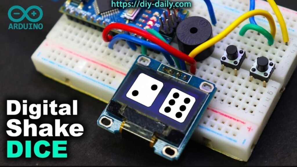
In this comprehensive tutorial, you will learn how to build your own Arduino Digital Shake Dice game. By combining an Arduino microcontroller, a crisp I2C OLED display, push buttons, and an active buzzer, this interactive gadget generates randomized dice rolls complete with visual readouts and sound effects.
Components Required
To assemble this project, gather the following hardware components:
- Arduino Nano or Uno
- 0.96-inch I2C OLED Display (128×64 pixels)
- Push Buttons (x2 or x1)
- Active Buzzer (for audio rolling feedback)
- Breadboard and Jumper Wires
- USB Cable for power and programming
Circuit Wiring Guide
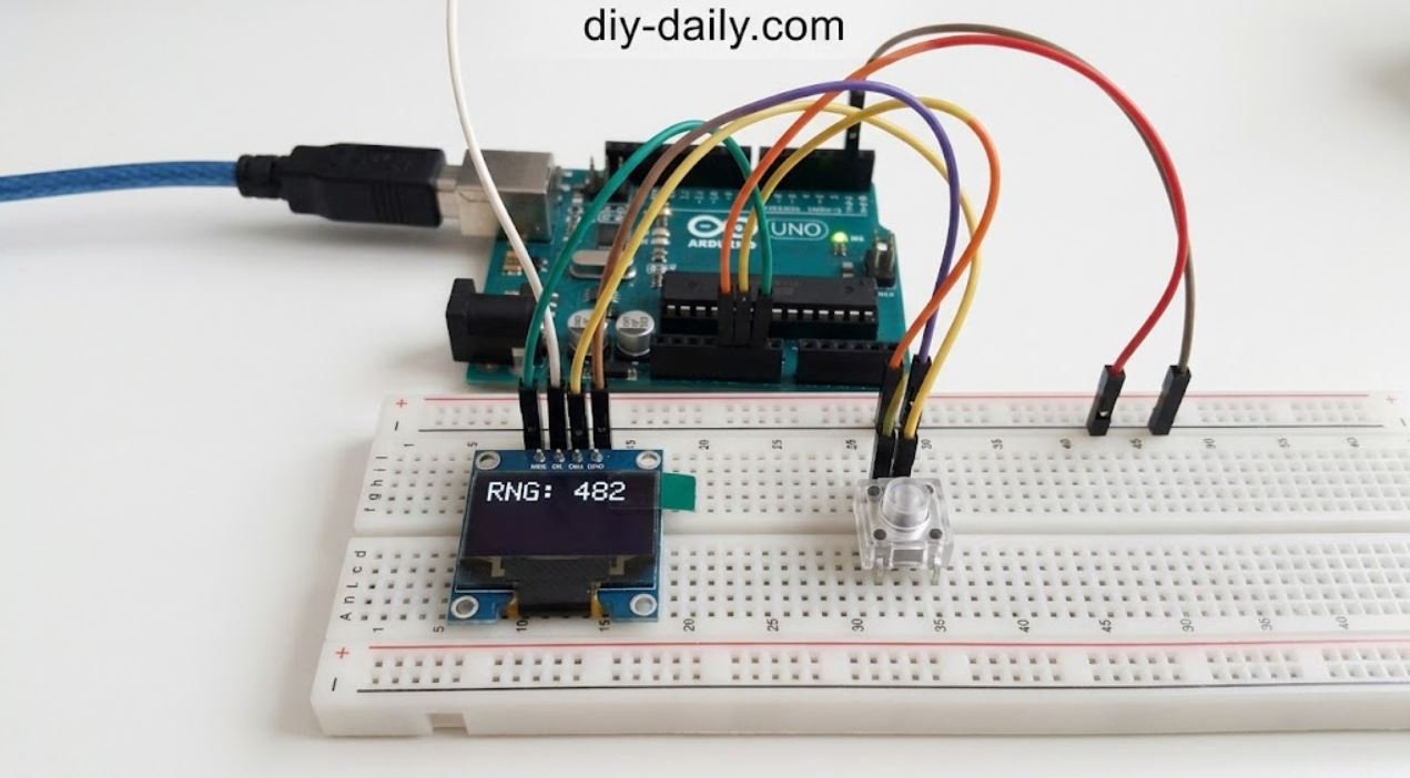
Connect your components to the Arduino according to the following mapping:
- OLED Display (I2C):
- VCC ===> 5V or 3.3V
- GND ===> GND
- SCL ===> A5 (SCL)
- SDA ===> A4 (SDA)
- Push Button:
- One terminal ===> Digital Pin 2 (configured with internal pull-up)
- Other terminal ===> GND
- Active Buzzer:
- Positive Pin ===> Digital Pin 8
- Negative Pin ===> GND
Arduino Source Code
Below is the complete, production-ready Arduino code for the digital shake dice. Make sure you install the Adafruit GFX, Adafruit SSD1306, and Wire libraries via the Arduino Library Manager before uploading.
#include <Wire.h>
#include <Adafruit_GFX.h>
#include <Adafruit_SSD1306.h>

#define SCREEN_WIDTH 128
#define SCREEN_HEIGHT 64
#define OLED_RESET    -1
Adafruit_SSD1306 display(SCREEN_WIDTH, SCREEN_HEIGHT, &Wire, OLED_RESET);

const int buttonPin = 2;
const int buzzerPin = 8;

void setup() {
  Serial.begin(115200);

  // Initialize pins
  pinMode(buttonPin, INPUT_PULLUP);
  pinMode(buzzerPin, OUTPUT);

  // Initialize I2C and OLED display
  Wire.begin();
  if(!display.begin(SSD1306_SWITCHCAPVCC, 0x3C)) {
    Serial.println(F("SSD1306 allocation failed"));
    for(;;);
  }

  // Seed random number generator using floating analog noise
  randomSeed(analogRead(0));

  // Splash Screen
  display.clearDisplay();
  display.setTextSize(1);
  display.setTextColor(SSD1306_WHITE);
  display.setCursor(15, 20);
  display.print("Digital Shake DICE");
  display.setCursor(25, 40);
  display.print("Press Button!");
  display.display();
  delay(2000);
}

void loop() {
  // Check if button is pressed
  if (digitalRead(buttonPin) == LOW) {
    // Trigger rolling feedback sound
    digitalWrite(buzzerPin, HIGH);

    // Animation / Rolling effect simulation
    for (int i = 0; i < 5; i++) {
      int tempDie1 = random(1, 7);
      int tempDie2 = random(1, 7);

      display.clearDisplay();
      display.setTextSize(1);
      display.setCursor(10, 5);
      display.print("ROLLING DICE...");

      display.setTextSize(3);
      display.setCursor(30, 25);
      display.print(tempDie1);
      display.print(" ");
      display.print(tempDie2);
      display.display();
      delay(80);
    }

    // Final random roll values
    int die1 = random(1, 7);
    int die2 = random(1, 7);

    // Turn off buzzer sound
    digitalWrite(buzzerPin, LOW);

    // Display final result
    display.clearDisplay();
    display.setTextSize(1);
    display.setCursor(10, 5);
    display.print("DIGITAL SHAKE DICE");

    display.setTextSize(3);
    display.setCursor(30, 25);
    display.print(die1);
    display.print(" ");
    display.print(die2);
    display.display();

    // Debounce delay
    delay(400);
  }
}How It Works
- Input Trigger: Pressing the button pulls the digital pin low, signaling the Arduino that a new dice roll has been requested. AVIF
- Randomization: The
random(1, 7)function generates pseudo-random numbers between 1 and 6 for two separate dice. - Display & Audio Output: The OLED screen updates rapidly to simulate a rolling animation, while the buzzer sounds briefly before displaying the final numerical outcome. AVIF
Conclusion
Building this Arduino digital shake dice game is a fun and rewarding beginner project that combines simple wiring, display programming, and logic handling. Once assembled, you can easily package it into a 3D-printed case and swap the push button for a mercury or tilt sensor to create a true “shake-to-roll” experience!