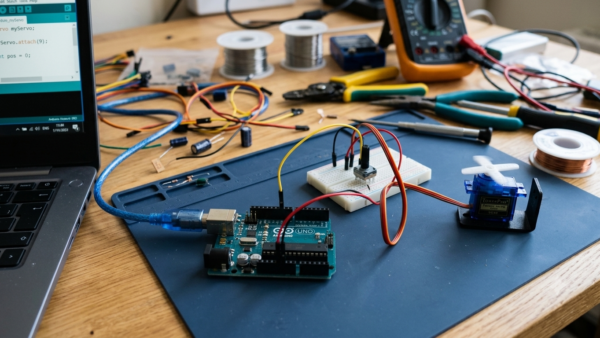
Every electronics journey starts the same way: with a single blinking LED. It is the “Hello, World” of hardware, and it teaches you more than you might expect. In this tutorial you will wire an LED to an Arduino Uno with the correct current-limiting resistor, upload your first sketch, and understand exactly what each line of code does. By the end you will control the blink speed, blink patterns, and have the confidence to move on to sensors and motors.
How the Blink Circuit Works
The Arduino Uno has 14 digital input/output pins. When you set one of them to OUTPUT and write it HIGH, the pin supplies 5 volts relative to ground. An LED (light-emitting diode) lights up when current flows through it in the forward direction, but it has almost no internal resistance — connect one directly to 5 V and it will draw far more current than it can survive. That is why we always place a resistor in series with the LED. For a standard red LED with a forward voltage of about 2 V, a 220 Ω resistor limits the current to roughly (5 − 2) / 220 ≈ 14 mA, which is bright, safe for the LED, and well within the Uno’s 20 mA per-pin recommendation.
Parts Needed
- Arduino Uno (or compatible board) with USB cable
- 1× 5 mm LED, any color
- 1× 220 Ω resistor (red–red–brown bands)
- 2× male-to-male jumper wires
- Small solderless breadboard
Wiring the LED
Identify the LED legs first: the longer leg is the anode (positive), the shorter leg is the cathode (negative), and the flat spot on the plastic rim marks the cathode side.
| Arduino Uno | Component | Notes |
|---|---|---|
| Digital pin 13 | 220 Ω resistor → LED anode (long leg) | Resistor position in series does not matter |
| GND | LED cathode (short leg) | Completes the circuit to ground |
The Blink Sketch
Open the Arduino IDE and paste this sketch. It is the classic Blink example, annotated so every line is clear.
// Blink an LED on pin 13 once per second.
const int LED_PIN = 13; // On-board LED is also on pin 13.

void setup() {
  pinMode(LED_PIN, OUTPUT); // Configure the pin as an output.
}

void loop() {
  digitalWrite(LED_PIN, HIGH); // LED on: pin supplies 5 V.
  delay(1000);                 // Wait 1000 milliseconds.
  digitalWrite(LED_PIN, LOW);  // LED off: pin drops to 0 V.
  delay(1000);                 // Wait again, then repeat.
}
Walkthrough
setup() runs once when the board powers up or resets; here we only tell the microcontroller that pin 13 will drive current. loop() then runs forever. digitalWrite() switches the pin between 5 V (HIGH) and 0 V (LOW), and delay() pauses the program. Because the pin also feeds the tiny on-board LED marked “L”, you will see your breadboard LED and the on-board LED blink together.
Uploading and Testing
- Connect the Uno with the USB cable. In the IDE, select Tools → Board → Arduino Uno.
- Select the correct port under Tools → Port (usually labelled “Arduino Uno”).
- Click the arrow button to compile and upload. You should see the TX/RX LEDs flicker, then your LED starts blinking once per second.
Experiments to Try
Change both delay() values to 100 for a fast strobe, or make them unequal (200 on, 1500 off) for a heartbeat pattern. Try blinking Morse code “SOS”: three short, three long, three short pulses. Move the wire from pin 13 to pin 8 and update LED_PIN — you have just learned the core skill of mapping hardware to software.
Try It in the Circuit Simulator
No hardware nearby? Build this exact circuit — battery or Arduino board, 220 Ω resistor and LED — in our Circuit Simulator and press Run to watch the current flow. Try different resistor values and see how the LED brightness responds; push the current above 30 mA and the simulator will even show you the LED burning out, so your real one does not have to.
Choosing Resistors for Other LED Colors
The 220 Ω figure is not universal — it comes from the red LED’s 2 V forward drop. Blue, white and green LEDs drop 3–3.4 V, so from 5 V the resistor only sees about 1.7 V, and 220 Ω yields a gentle 8 mA. For maximum brightness from a blue LED use 100 Ω: (5 − 3.2) / 100 = 18 mA. Yellow and old-style green LEDs sit near 2.2 V, close enough to red that the same resistor works. Whenever you change the supply or the LED, redo this one-line calculation — it takes ten seconds and is the difference between a circuit that lasts years and one that dies in a drawer.
Troubleshooting
- LED does not light: flip the LED around — it only conducts in one direction. Check that the resistor actually connects pin 13 to the anode.
- Upload fails with “port not found”: try a different USB cable (some are charge-only), a different USB port, or reinstall the board drivers.
- LED is very dim: you may have grabbed a 10 kΩ resistor by mistake; check the color bands.
- LED lit before uploading: a previous program may still be running on the board — that is normal.
Safety Notes
- Never connect an LED directly between 5 V and GND without a resistor.
- Do not power the Uno from USB and an external supply at the same time unless you know what you are doing.
- Keep jumper wires tidy so nothing shorts against the metal USB connector on the board.
Conclusion
You have wired your first circuit, uploaded your first sketch, and learned how a pin, a resistor and an LED work together. Every Arduino project — robots, weather stations, home automation — is built from these same primitives. Next, learn to read input with our pushbutton tutorial, and the LED can respond to your finger instead of a timer.