Resistors obey Ohm’s law instantly. Capacitors add the dimension of time: they store charge, release it later, and in doing so create delays, fades and filters. The simplest possible demonstration is also genuinely beautiful — press a button, an LED lights; release it, and the LED fades out gracefully over a second instead of snapping off. In this tutorial you will build that circuit, understand the RC time constant behind the fade, and even measure the discharge curve with an Arduino.
What a Capacitor Actually Does
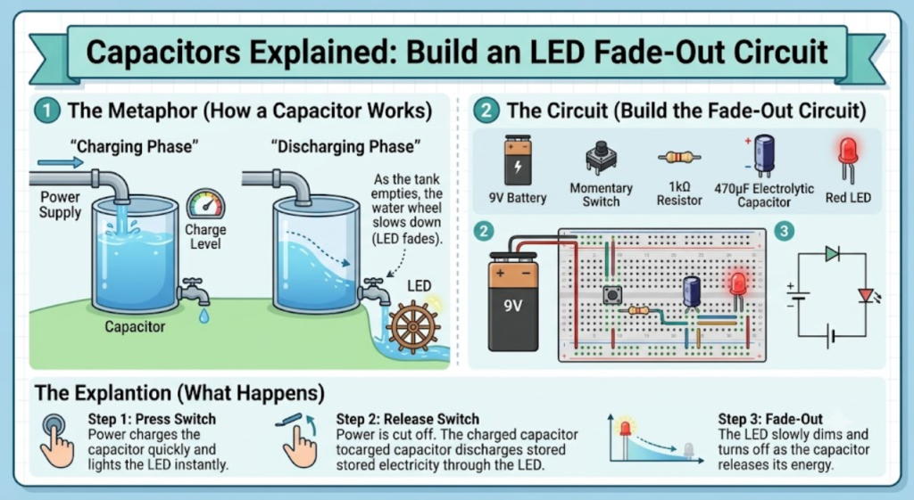
A capacitor is two conductive plates separated by an insulator. Connected to a voltage, charge piles onto the plates until the capacitor’s voltage equals the source — then current stops. Disconnected, it holds that charge like a tiny, fast, rechargeable battery. Capacity is measured in farads; a 1000 µF capacitor stores a thousand times more charge per volt than a 1 µF part, so it fades your LED ten times longer. The discharge is not linear: voltage falls exponentially, losing about 63% of what remains every τ = R × C seconds. For 1000 µF through 1 kΩ, τ = 1 second — which you can literally watch.
Parts Needed
- 1× 5 V supply (USB or Arduino 5V pin)
- 1× 1000 µF electrolytic capacitor (mind the stripe — that leg is negative)
- 1× 5 mm LED and 1× 220 Ω resistor
- 1× 1 kΩ resistor
- 1× pushbutton
- Breadboard, jumper wires; Arduino Uno optional for curve plotting
Wiring the Fade-Out Circuit
The button charges the capacitor instantly from 5 V; when released, the capacitor discharges through the 1 kΩ resistor, LED and its 220 Ω resistor, fading the LED as its voltage decays.
| Component | Connection A | Connection B | Notes |
|---|---|---|---|
| Pushbutton | 5V | Capacitor + | Press = charge instantly |
| 1000 µF cap | + to button / LED node | − to GND | Stripe marks the negative leg |
| 1 kΩ resistor | Capacitor + | LED anode node | Sets fade time with the cap |
| LED + 220 Ω | From 1 kΩ node | GND | 220 Ω limits peak LED current |
Press, Release, Watch
Hold the button for a second — the cap charges to 5 V and the LED is bright. Release: the LED fades smoothly to dark over roughly three seconds (about 3τ for 1 kΩ × 1000 µF, with the LED’s 2 V drop ending the visible glow early). Swap in a 470 µF cap and the fade halves; a 10 kΩ resistor stretches it to ten seconds. You are now designing with τ = RC — the same equation behind camera flashes, power-supply smoothing and the 555 timer in our advanced tutorials.
Measure the Curve with an Arduino
Connect the capacitor’s positive node to A0 through a wire (A0’s high input resistance barely disturbs the measurement) and run this sketch, pressing and releasing the button while the Serial Plotter draws the exponential decay:
const int SENSE_PIN = A0;

void setup() {
  Serial.begin(9600);
  Serial.println("CapVoltage(V)");
}

void loop() {
  int raw = analogRead(SENSE_PIN);
  float volts = raw * (5.0 / 1023.0);
  Serial.println(volts, 2);
  delay(50); // 20 samples per second.
}
The plotter shows a sharp jump to 5 V on press, then the classic exponential sag. Pick two points — say, the time to fall from 5 V to 1.84 V (36.8%) — and you have measured τ experimentally. Compare it to R × C and feel the theory land.
Try It in the Circuit Simulator
The Circuit Simulator models capacitor charge and discharge with an RC curve: place a battery, switch, resistor, capacitor and LED, then open the switch after charging and watch the LED fade in real time. Try several RC values back to back — it is far faster than swapping physical parts while you build intuition for tau.
Troubleshooting
- LED never lights: electrolytic capacitor backwards (stripe to positive) — reversed electrolytics heat up, vent and can burst; replace it and rewire.
- Fade is instant: capacitor value far smaller than intended, or the 1 kΩ is actually 100 Ω — check the bands.
- LED stays dim forever: capacitor is leaking or the button never fully connects — test the cap by charging it and measuring its held voltage after 30 s.
- Arduino reads noise: keep the A0 wire short and share ground between the sensor circuit and the Arduino.
Safety Notes
- Electrolytic capacitors are polarized — reverse voltage causes heating, venting and occasionally a loud pop; always respect the stripe.
- Large capacitors (power-supply size) can hold dangerous charge long after power is removed — discharge them through a resistor before handling; this tutorial’s 1000 µF at 5 V is harmless.
- Never short a charged capacitor with a wire — the spark pits the terminals and stresses the part.
Conclusion
You have built time itself into a circuit: one capacitor turned a binary button into an analog fade, and τ = RC predicted it. This same charge-discharge behavior smooths your power rails, debounces switches, and sets the tempo of the 555 timer flasher in our Advanced Electronics track — the perfect next read.