The multimeter is the stethoscope of electronics: it tells you what a circuit is actually doing instead of what you hope it is doing. Yet most beginners use maybe 10% of its ability — and a fair number blow its fuse on day one by measuring current the wrong way. This tutorial walks through voltage, current, resistance, continuity and diode mode with real things to measure at each step, plus the safety habits that keep both you and the meter alive.
Anatomy of the Meter
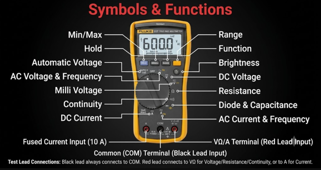
Every handheld meter shares the same layout: a rotary dial to select the quantity and range, a display, and (usually) three probe jacks. COM takes the black lead, always. VΩmA takes the red lead for voltage, resistance and small currents. 10A is a separate, unfused-or-separately-fused jack for big currents. The single most important habit in this entire tutorial: check where the red lead is plugged in before you touch the probes to anything.
Parts Needed
- Any digital multimeter (an inexpensive auto-ranging model is fine)
- 1× 9 V battery and a 1.5 V AA cell
- Assorted resistors, 1× LED, jumper wires, breadboard
- A length of wire to test continuity
Measuring Voltage: In Parallel, Circuit Powered
Voltage is the difference between two points, so the meter connects across them while the circuit lives on. Dial to V (DC, the symbol with straight lines), red lead in VΩ. Measure the AA cell (≈1.5 V), then the 9 V battery (≈9.5 V fresh). Now power the LED circuit and measure across the LED (≈2 V, its forward voltage) and across its resistor (≈7 V) — together they equal the battery. Touching the probes to the wrong polarity only shows a minus sign; harmless. Voltage mode presents very high resistance, so it cannot disturb the circuit — measure fearlessly.
Measuring Current: In Series, Circuit Broken
Current flows through things, so the meter must become part of the path: break the circuit, insert the meter in the gap. Red lead in mA (or 10A for anything above your mA range), dial to A/mA. In the LED circuit, expect about 14 mA through the loop. Now the classic disaster to avoid: if the leads are in the current jacks and you poke them across a battery (parallel), the meter is a near-short — its internal resistance is a fraction of an ohm. The fuse (hopefully) dies instantly. This is the mistake that kills beginner meters, and it happens exactly once if you are lucky. After any current measurement, move the red lead back to VΩ immediately.
Measuring Resistance: Circuit Off, Component Isolated
The ohm range works by pushing a tiny known current through the part and measuring the resulting voltage — so the circuit must be unpowered, and ideally lift one leg of the component out of the board so parallel paths do not corrupt the reading. Measure a 1 kΩ resistor (expect 950–1050 Ω for 5% tolerance), then hold both probe tips against your fingers: you just measured your own body resistance, typically 100 kΩ to a few MΩ depending on dry or damp skin — which is why you never grip both component leads while measuring.
Continuity and Diode Mode: The Two Hidden Gems
Continuity mode (sound-wave symbol) beeps when resistance between the probes is low — use it unpowered to find broken wires, confirm solder joints and trace breadboard rows. Diode mode (arrow-with-bar symbol) pushes a small test current and shows the forward drop: a red LED reads ≈1.8–2.2 V one way, overload the other, confirming both health and polarity in one touch. A silicon diode reads ≈0.6 V; a shorted one reads near zero both ways.
Quick Reference Table
| Quantity | Lead Jacks | Circuit State | Meter Connects |
|---|---|---|---|
| Voltage (V) | COM + VΩ | Powered | In parallel across two points |
| Current (A/mA) | COM + mA or 10A | Powered, loop broken | In series inside the path |
| Resistance (Ω) | COM + VΩ | Unpowered, part isolated | Across the component |
| Continuity / Diode | COM + VΩ | Unpowered | Across the path or diode |
Try It in the Circuit Simulator
Not sure what a circuit should read before probing it? Build it first in our Circuit Simulator and note the current the status bar reports. Walking to the bench with an expected number — “this loop should draw about 14 mA” — turns measurement from guesswork into verification.
Troubleshooting
- Everything reads zero on mA: blown internal fuse from a past parallel current mistake — open the back and replace the ceramic fuse with the exact rated type.
- Voltage readings suspiciously low: weak 9 V battery inside the meter; replace it before doubting your circuit.
- Ohms reads overload on a good part: part exceeds the selected manual range — range up or switch to auto.
- Continuity beeps with nothing connected: probe leads are touching each other or the lead is shorted internally.
Safety Notes
- Never measure resistance, continuity or diodes on a live circuit.
- For anything above 30 V, and especially mains, use a meter with a proper CAT II/CAT III rating, intact probes and one hand in your pocket — or better, leave mains to licensed electricians while you learn on batteries.
- Never use the 10A jack on a circuit you have not estimated first.
Conclusion
Voltage in parallel on a live circuit, current in series through a broken loop, resistance on a dead and isolated part — three sentences that cover 95% of meter work. With these skills every other tutorial on this site becomes verifiable: when a project misbehaves, you now ask the circuit what it is doing, and it answers honestly.