An LDR (light-dependent resistor) in a divider gives you a voltage that wanders maybe a volt between shadow and sunlight. Feed that to a microcontroller and you burn most of the ADC range doing nothing. The operational amplifier exists to fix exactly this: it amplifies the interesting part of a signal to fill the range you can measure. In this tutorial you will build a non-inverting amplifier around the LM358, set its gain with two resistors, and read the result on an Arduino — learning the two golden rules that make every op-amp circuit analyzable.
The Golden Rules and the Gain Formula
An op-amp has two inputs (+ and −) and one output. With negative feedback — a path from output back to the − input — two rules hold: (1) the inputs draw essentially no current, and (2) the amplifier forces its two inputs to the same voltage. In the non-inverting configuration, the signal goes to the + input, while the − input sits on a divider (R1 to ground, R2 to output) that samples the output. Rule 2 then dictates: output = input × (1 + R2/R1). With R1 = 10 kΩ and R2 = 47 kΩ, gain is 5.7 — a 0.7 V wiggle becomes a 4 V swing your ADC can actually resolve. The LM358 is the beginner’s friend because it runs from a single 5 V supply and its inputs work down to ground, though its output tops out around 3.5 V on a 5 V rail — choose your gain so the signal never clips against that ceiling.
Parts Needed
- 1× LM358 dual op-amp (DIP-8)
- 1× LDR (photoresistor), 1× 10 kΩ fixed resistor (divider)
- 1× 10 kΩ (R1) and 1× 47 kΩ (R2) for the gain network
- 1× 100 nF capacitor (supply decoupling), 1× LED + 220 Ω (optional indicator)
- Arduino Uno, breadboard, jumper wires, flashlight or phone torch
Wiring the Amplifier
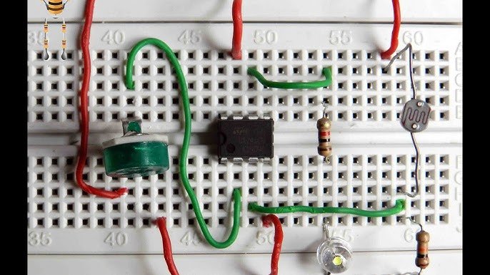
The LM358 contains two amplifiers; we use one and park the other safely. Pins: 1 out-A, 2 inA−, 3 inA+, 4 GND, 8 VCC (check the datasheet dot/notch for pin 1).
| Element | Connection A | Connection B | Notes |
|---|---|---|---|
| LDR | 5V | Divider node | Resistance falls with light |
| 10 kΩ divider | Divider node | GND | Node rises with light |
| Divider node | Pin 3 (inA+) | — | The signal input |
| R1 10 kΩ | Pin 2 (inA−) | GND | Gain leg 1 |
| R2 47 kΩ | Pin 1 (out) | Pin 2 (inA−) | Feedback; gain = 5.7 |
| Pin 8 / Pin 4 | 5V | GND | 100 nF across them at the chip |
| Pin 1 (out) | Arduino A0 | — | Amplified light level |
| Unused amp (pins 5,6,7) | Pin 5 to GND, pin 6 to pin 7 | — | Follower-at-ground keeps it quiet |
The Reader Sketch
const int LIGHT_PIN = A0;

void setup() {
  Serial.begin(9600);
  Serial.println("RawADC Voltage");
}

void loop() {
  int raw = analogRead(LIGHT_PIN);
  float v = raw * (5.0 / 1023.0);

  Serial.print(raw);
  Serial.print("t");
  Serial.println(v, 2);

  delay(200);
}
Calibrating on the Bench
Open the Serial Plotter and play torch and shadow over the LDR. In full dark the divider sits near 0 V and the output follows near 0 V (the LM358 gets close to its negative rail); under a bright torch the divider may reach ≈0.6–0.8 V and the output swings to 3.4 V+ — most of the ADC’s 0–5 V span now carries signal instead of waste. Compare with reading the raw divider directly: you have multiplied your usable resolution by the gain, for the price of two resistors.
Where This Goes Next
Swap R2 for a 100 kΩ trimmer and gain becomes adjustable; add a capacitor across R2 and you have built a low-pass filter that smooths flicker. The same circuit amplifies thermistors, strain gauges and microphone capsules — only the front-end divider changes. Prototype the divider’s behavior and confirm its voltage range in our Circuit Simulator before choosing the gain resistors.
Three Circuits, One Chip
The LM358’s second amplifier is not spare parts — it is an invitation. Reconfigure it as a voltage follower (output tied straight to inA−, signal into inA+) and it buffers a weak signal without loading it, a gift for high-impedance sensors. Remove the feedback and add a reference voltage to the − input, and the same chip becomes a comparator that snaps its output high or low when light crosses a threshold — an instant dusk detector for a night-light. Amplifier, buffer, comparator: three of the five most-used analog building blocks, all from one eight-pin chip and the two golden rules you learned today.
Troubleshooting
- Output stuck at ≈3.5 V: clipping — gain too high or divider voltage too large; reduce R2 or swap the divider resistor.
- Output stuck near 0 V: feedback open (R2 not connected pin 1 to pin 2) or the chip is in backwards — check the pin-1 notch.
- Output noisy: missing decoupling and long divider wires; add 100 nF at the supply pins and shorten the input lead.
- Gain does not match the formula: at high gains the LM358’s limited bandwidth rolls off — keep gain under ≈20 for clean results.
Safety Notes
- Single 5 V supply only for this circuit; reversed supply kills the LM358 instantly.
- Never feed an op-amp input a voltage beyond its supply rails.
- The LM358 cannot output near 5 V — do not design circuits that require it; choose a rail-to-rail part instead.
Conclusion
Two golden rules and one divider gave you gain = 1 + R2/R1 — and a sensor signal that finally fills the ADC. Op-amps are the connective tissue of analog electronics: buffers, filters, comparators and oscillators are all this same chip with different feedback. Next, take everything you have prototyped and make it permanent with our PCB design workflow.