If electronics had one equation to rule them all, it would be V = I × R. Ohm’s law connects voltage, current and resistance, and nearly every design decision on a workbench — which resistor, how hot, how bright — comes back to it. Reading about it is one thing; measuring it yourself is another. In this tutorial you will run three quick experiments with a battery, resistors and a multimeter, and watch the numbers match the theory to within a few percent.
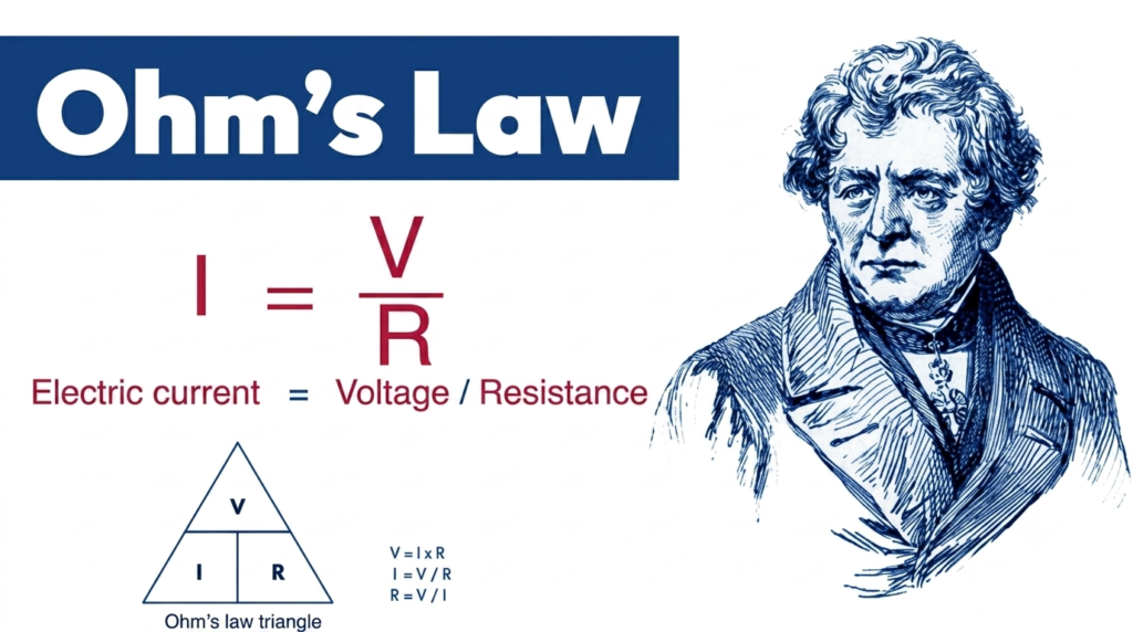
The Triangle You Will Use Forever
Voltage (V, in volts) is the push, current (I, in amps) is the flow, and resistance (R, in ohms, Ω) is the opposition. Cover the quantity you want in the V–I–R triangle and the formula appears: I = V / R, R = V / I, V = I × R. There is a fourth member of the family, power: P = V × I, which tells you whether your resistor will stay cool or cook. Memorize these four and you can analyze 90% of beginner circuits on a napkin.
Parts Needed
- 1× 9 V battery with snap connector (or a 5 V USB supply)
- Resistors: 220 Ω, 470 Ω, 1 kΩ
- 1× 5 mm LED (for the power experiment)
- Digital multimeter
- Breadboard and jumper wires
Experiment 1: Predict the Current, Then Measure It
Wire the battery through the 1 kΩ resistor and back — a single loop. Ohm’s law predicts I = 9 V / 1000 Ω = 9 mA. Now break the loop and insert your multimeter in series, set to the mA range: you should read very close to 9 mA (battery voltage droops slightly under load, so 8.5–9 mA is a perfect score). Repeat with 470 Ω (expect ≈19 mA) and 220 Ω (expect ≈41 mA).
| Resistance | Predicted I = V/R | Typical Measured |
|---|---|---|
| 1000 Ω | 9.0 mA | 8.6–9.2 mA |
| 470 Ω | 19.1 mA | 18–20 mA |
| 220 Ω | 40.9 mA | 39–42 mA |
Experiment 2: Voltage Divides Across Series Resistors
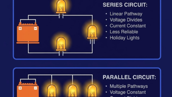
Put the 1 kΩ and 470 Ω resistors in series across the battery. Total resistance 1470 Ω, so current is 9 / 1470 ≈ 6.1 mA everywhere in the loop. Now measure voltage across each resistor with the meter in parallel: you should find about 6.1 V across the 1 kΩ and 2.9 V across the 470 Ω — and notice they add back up to the battery voltage. This is the voltage divider rule hiding inside Ohm’s law, and it is how sensors like LDRs are read.
Experiment 3: Power, the Part That Gets Hot
Wire the LED with the 220 Ω resistor to 9 V. The LED drops about 2 V, leaving 7 V across the resistor, so I = 7 / 220 ≈ 32 mA — actually too much for a standard LED (20 mA rating), which is why it will look extremely bright and run warm. Resistor power: P = 7 V × 0.032 A ≈ 0.22 W, right at the edge of a standard 0.25 W part — touch it after a minute and you will feel Ohm’s law. Swap in 470 Ω and everything calms down: 15 mA, comfortable LED, cool resistor. This experiment is why real designs start with a power check.
Try It in the Circuit Simulator
All three experiments translate directly to our Circuit Simulator — place a battery and resistor, press Run, and read the current in the status bar. Crank the resistor down toward zero and watch the current climb toward a short-circuit warning; it is the safest way possible to develop a healthy fear of low resistance.
Troubleshooting
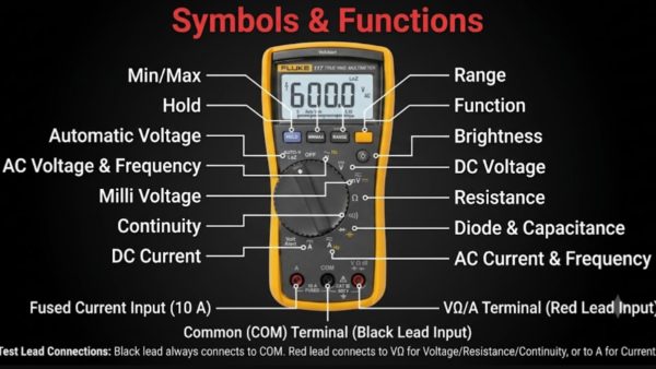
- Meter reads 0.00 on current range: the meter must be in series (break the loop); also check the lead is in the mA jack, not just COM and VΩ.
- Current way off prediction: verify the resistor with the meter’s ohm range first — 5% tolerance is real, and misread bands are common.
- Battery voltage reads 8 V: partially flat battery; recalculate predictions with the measured voltage, not the label.
- Numbers drift while measuring: poor contact on clips or breadboard springs — press firmly.
Safety Notes
- Never measure current by putting the meter across the battery in current mode — that is a near-short and can blow the meter’s fuse or worse.
- Keep to batteries and USB supplies while learning; do not practice Ohm’s law on mains or wall adapters above 12 V.
- A resistor that is too hot to touch is telling you the power rating is exceeded — unplug and recalculate.
Conclusion
V = IR stopped being abstract the moment your meter agreed with your pencil. You can now predict current, split voltage, and check power — the three calculations behind every circuit in every tutorial on this site. Keep the 9 V battery and meter handy: the resistor color-code tutorial is the natural next step.