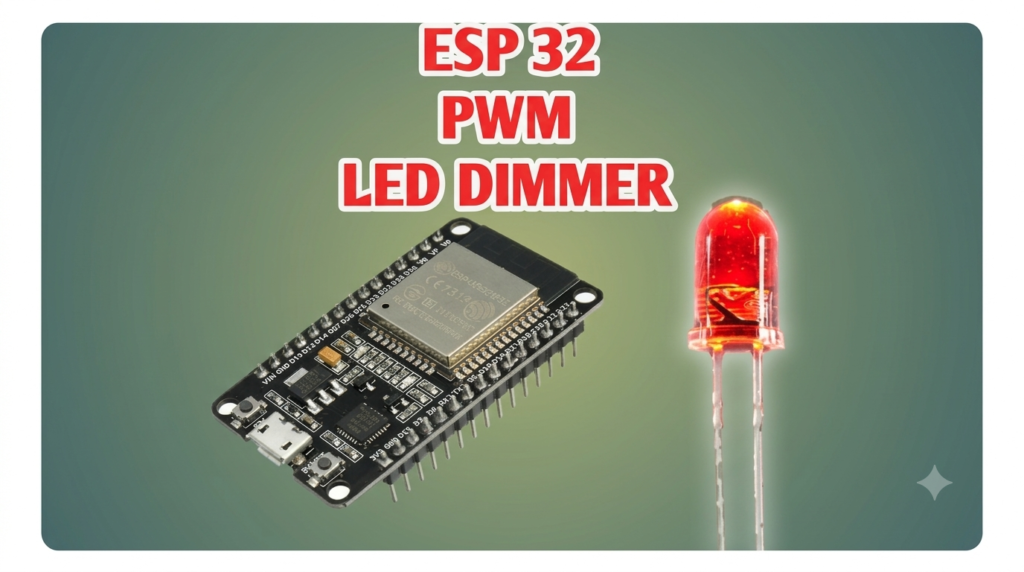
Digital pins give you ON and OFF. PWM — pulse-width modulation — gives you everything in between. By switching a pin thousands of times per second and varying the on-time fraction (the duty cycle), an LED’s average brightness follows your command. The ESP32 takes this further than classic Arduinos: up to 16 independent PWM channels at configurable frequency and resolution. In this tutorial you will dim one LED smoothly, then cross-fade an RGB LED through the rainbow — and learn why a gamma curve makes the result look professional.
Frequency, Resolution, Duty Cycle
Three numbers define a PWM channel. Frequency is how many on/off cycles happen per second; for LEDs, 5 kHz is safely above visible flicker. Resolution is how many brightness steps exist — 8 bits gives 256 levels (0–255), 13 bits gives 8192. The trade-off is real: maximum frequency times 2resolution cannot exceed the 80 MHz clock, so 13 bits caps you near 9.7 kHz. Duty cycle is the on-time percentage: 128/255 ≈ 50% power. One more subtlety: human brightness perception is logarithmic — level 128 looks far brighter than half. Applying a gamma correction (brightness2.2, scaled back to your range) makes fades feel linear and expensive.
Parts Needed
- ESP32 dev board with USB cable
- 1× common-cathode RGB LED (or three separate LEDs)
- 3× 220 Ω resistors
- Breadboard and jumper wires
Wiring the RGB LED
A common-cathode RGB LED has four legs: the longest is the shared cathode (to GND); the other three are the red, green and blue anodes, each needing its own resistor.
| ESP32 | Component | Notes |
|---|---|---|
| GPIO 16 | 220 Ω → red anode | Channel R |
| GPIO 17 | 220 Ω → green anode | Channel G |
| GPIO 18 | 220 Ω → blue anode | Channel B |
| GND | Common cathode (long leg) | Shared ground |
The Rainbow Fade Sketch
ESP32 Arduino core 3.x simplified PWM to ledcAttach(pin, freq, resolution) and ledcWrite(pin, duty) — no manual channel management. (On older 2.x cores the equivalent is ledcSetup(channel, freq, res) plus ledcAttachPin(pin, channel).)
const int PIN_R = 16, PIN_G = 17, PIN_B = 18;
const int FREQ = 5000, RES_BITS = 8;   // 5 kHz, 256 levels.

// Gamma-correct 0..255 perceived brightness to a duty value.
int gamma255(int level) {
  float g = pow(level / 255.0, 2.2);
  return (int)(g * 255.0 + 0.5);
}

void setColor(int r, int g, int b) {
  ledcWrite(PIN_R, gamma255(r));
  ledcWrite(PIN_G, gamma255(g));
  ledcWrite(PIN_B, gamma255(b));
}

void setup() {
  ledcAttach(PIN_R, FREQ, RES_BITS);
  ledcAttach(PIN_G, FREQ, RES_BITS);
  ledcAttach(PIN_B, FREQ, RES_BITS);
}

void loop() {
  // Walk hue around the color wheel.
  for (int hue = 0; hue < 360; hue++) {
    int sector = hue / 60;          // 0..5
    int x = (hue % 60) * 255 / 60;  // 0..255 within the sector
    switch (sector) {
      case 0: setColor(255, x, 0); break;
      case 1: setColor(255 - x, 255, 0); break;
      case 2: setColor(0, 255, x); break;
      case 3: setColor(0, 255 - x, 255); break;
      case 4: setColor(x, 0, 255); break;
      default: setColor(255, 0, 255 - x); break;
    }
    delay(10);
  }
}
Walkthrough
Attaching each pin starts a hardware PWM timer; after that, ledcWrite() is instant and glitch-free because the duty lives in hardware. The loop walks the HSV color wheel’s six sectors — ramping one channel up while another ramps down gives smooth transitions through red, yellow, green, cyan, blue, magenta and back. The gamma table is the finishing touch: comment gamma255() out and watch the fade turn jerky, racing through bright colors and crawling through dark ones. For production code, precompute the 256 gamma values once in setup() or store them in a lookup table instead of calling pow() every frame.
Try It in the Circuit Simulator
Wire the three LED-plus-resistor legs in our Circuit Simulator first and confirm each channel’s current at full brightness — about (3.3 − 2.0) / 220 ≈ 6 mA for red. Knowing the current per channel matters when you scale up to LED strips and drivers.
PWM Beyond LEDs
The same ledc hardware drives much more than brightness. A piezo buzzer connected through a 100 Ω resistor becomes a speaker: set the duty to 50% and sweep the frequency to play tones — 440 Hz is concert A, and melodies are just timed frequency tables. A servo can be driven directly with a 50 Hz frequency and 13–16 bit resolution, mapping pulse widths of 500–2500 µs into duty values — no Servo library needed. DC motor speed control works through a MOSFET or driver IC at 20 kHz (above hearing, so motors do not whine). In every case the mental model is identical: frequency sets the rhythm, duty cycle sets the average energy, and the load’s inertia — thermal, mechanical or acoustic — smooths the pulses into something continuous.
Troubleshooting
- Visible flicker: frequency too low — raise to 5 kHz, or drop resolution to keep the clock math legal.
- LED never fully off: confirm you write duty 0 (not just a tiny value) and that no other library reconfigured the pin.
- Wrong colors: you have a common-anode RGB LED — wire its common leg to 3V3 and invert every duty value.
- Colors jump between steps: add the gamma correction and shrink the delay to 10 ms.
ledcAttachundefined: you are on core 2.x — useledcSetup/ledcAttachPininstead.
Safety Notes
- One resistor per channel, always — sharing one resistor across parallel LEDs causes uneven current and early failure.
- GPIO pins source about 12 mA comfortably (40 mA absolute max); for LED strips use a MOSFET driver, never a bare pin.
- PWM into motors or solenoids needs flyback diodes — bare LEDs only for this tutorial.
Conclusion
PWM turns three digital pins into sixteen million colors, and the frequency/resolution/gamma trio is the whole craft. The same technique dims room lights, controls motor speed through drivers, and generates audio tones. Combined with the web server tutorial, your phone can now pick any color for your desk lamp — a genuinely useful gadget built from four parts.