Every project eventually outgrows USB cables and battery snaps: you have a 9–12 V source and a circuit that demands a steady 5 V. The classic answer is the 7805 linear regulator — three pins, two capacitors, done. But “done” hides important design questions: how much heat will it shed, why those exact capacitors, and when should you reach for a switching regulator instead? In this tutorial you will build a proper 5 V rail and make those decisions with numbers, not folklore.
How the 7805 Earns Its Keep
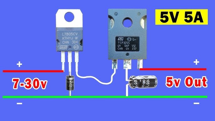
The 7805 is a self-contained feedback loop: it compares its output against an internal reference and adjusts a series pass transistor to hold 5 V regardless of input (7–25 V) or load (up to 1–1.5 A with a heatsink). The cost is efficiency: the excess voltage times the load current becomes heat inside the regulator. From 12 V at 300 mA, that is (12 − 5) × 0.3 = 2.1 W — enough to burn your finger and trip the chip’s thermal shutdown without a heatsink. The rule of thumb: below about 500 mW of dissipation a bare TO-220 survives in free air; beyond that, bolt on metal. Also respect dropout: the 7805 needs its input roughly 2 V above the output, so 7 V is the true minimum, not 5 V.
Parts Needed
- 1× 7805 regulator (TO-220)
- 1× 0.33 µF ceramic or film capacitor (input)
- 1× 0.1 µF ceramic capacitor (output)
- 1× 470 µF electrolytic (optional bulk reservoir)
- Heatsink for loads above ≈300 mA, 9–12 V DC supply
- Load for testing: USB-powered gadget, or 47 Ω 2W resistor (≈100 mA)
- Multimeter; breadboard is only suitable for small currents
Wiring the Rail
Facing the 7805’s printed side, legs are: input, ground, output — left to right. Keep both ceramic capacitors close to the pins with short leads; they exist to keep the regulator’s internal loop from oscillating, not to store energy.
| Element | From | To | Notes |
|---|---|---|---|
| Input supply + (9–12 V) | 7805 pin 1 (IN) | — | Observe polarity |
| 0.33 µF | Pin 1 | GND | Within a few mm of the pins |
| 7805 pin 2 (GND) | Ground rail | — | Shared by input and output |
| 0.1 µF | Pin 3 (OUT) | GND | Stability capacitor, mandatory |
| 470 µF (optional) | Pin 3 | GND | Smooths load transients; watch polarity |
| Load | Pin 3 (5 V) | GND | — |
Verify Like a Professional
- No-load check: power up and measure the output — expect 4.9–5.1 V. Anything else means a wiring error; power down and recheck.
- Load regulation: attach the 47 Ω load (≈106 mA) and confirm the output sags no more than ≈50 mV.
- Line regulation: vary the input from 8 V to 12 V if your supply allows; the output should barely move.
- Thermal check: run the load for five minutes and (carefully) feel the tab. Too hot to keep a finger on means heatsink time — or a switching regulator.
Linear vs. Switching: The Real Decision
Use a linear 7805 when the input-output gap is small, current is modest, and simplicity or low noise matters (audio, sensors, references). Switch to a buck converter module (MP1584, LM2596) when dropping from high voltage, drawing more than ≈500 mA, or running on batteries — 90% efficiency beats 42% every time. Many professional designs use both: a buck to get from 12 V to 6.5 V, then a linear regulator for the final clean 5 V. You can prototype the load side — your resistors and LEDs on a 5 V rail — in our Circuit Simulator to confirm current draw before choosing the regulator.
The Rest of the 78xx Family
Everything learned here scales across the family: the 7809 and 7812 deliver 9 V and 12 V rails with the same pinout, capacitors and dropout math, and their negative-voltage cousins (7905 and friends) mirror the layout but with different pin order — check the datasheet every single time. For low-dropout needs, an LM2940 or AMS1117 works with the input barely above the output (the AMS1117-5.0 accepts 6 V in), which is why they dominate battery projects. And if you need an adjustable rail, the LM317 sets any voltage from 1.25 V up with two resistors — the same feedback idea as the 7805, just with the divider brought outside for you to choose.
Troubleshooting
- Output equals input (≈12 V): regulator pins reversed or chip dead — disconnect immediately before the load cooks.
- Output oscillates or chatters: missing/misplaced 0.1 µF output capacitor; add it right at the pins.
- Output collapses under load: thermal shutdown cycling — reduce the voltage drop, add a heatsink, or switch to a buck.
- Works on the bench, fails in the box: no airflow around the regulator; convection needs vents.
Safety Notes
- The TO-220 tab is connected to ground on the 7805 but not on every regulator — check before letting heatsinks touch other metal.
- Heatsinks get hot by design; keep them clear of wires and fingers.
- Fuse the input when powering from large batteries or wall adapters capable of several amps.
Conclusion
A 5 V rail is three pins deep, but now you know what is underneath: dropout voltage, dissipation math, stability capacitors and the linear-versus-buck trade. Power is the least glamorous part of a project and the first thing that fails when ignored — design it deliberately and the rest of your circuits get to do their jobs.