
An Arduino pin delivers 20 mA at 5 V. A 12 V motor, a strip of fifty LEDs or a relay coil wants ten times that — at the wrong voltage. The bridge between those worlds is the humble NPN transistor used as a switch: a few milliamps into the base controls a hundred times more through the collector. In this tutorial you will calculate a base resistor properly, drive a real load with a 2N2222, and learn why every inductive load needs a flyback diode — with an Arduino sketch to run the whole thing.
The Transistor as a Switch
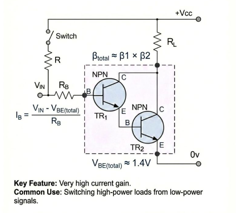
A bipolar transistor has three legs: base, collector, emitter. Current into the base-emitter junction (≈0.7 V drop, like a diode) switches on a much larger collector-emitter current, with the ratio approximated by hFE (current gain, 100–300 for a 2N2222). For switching we do not want proportional control — we want the transistor slammed fully on (saturated), where the collector-emitter drop falls to ≈0.2 V and almost no power heats the transistor. The design rule: calculate the minimum base current needed (load current / hFE), then multiply by 5–10 to guarantee saturation. Driving a 100 mA load with a pessimistic hFE of 50 needs 2 mA; we supply 10 mA, giving R = (5 − 0.7) / 0.01 = 430 Ω — so 470 Ω or 1 kΩ both work fine.
Parts Needed
- Arduino Uno with USB cable
- 1× 2N2222 or BC547 NPN transistor
- 1× 1 kΩ resistor (base), 1× 1N4007 diode (flyback)
- Load: 12 V PC fan, relay module coil, or 8–10 LEDs in parallel with resistors
- 12 V supply for the load (or 9 V battery for small fans)
- Breadboard, jumper wires, multimeter
Wiring the Low-Side Switch
The load lives between the positive supply and the collector; the emitter goes to ground. This “low-side” arrangement is why NPN switching is so easy: the base only ever sees the Arduino’s 5 V relative to ground.
| Component | Connection A | Connection B | Notes |
|---|---|---|---|
| Arduino D8 | 1 kΩ resistor | Transistor base | Sets ≈4 mA base current |
| Transistor emitter | GND rail | — | 2N2222: flat side facing you, legs are E-B-C left to right (check your datasheet) |
| Transistor collector | Load negative | — | Switches the ground side of the load |
| Load positive | +12 V supply | — | Load’s own voltage, not Arduino 5V |
| 1N4007 diode | Across load: cathode (stripe) to +12 V | Anode to collector | Mandatory for motors/relays |
| Arduino GND | 12 V supply GND | — | Common ground is essential |
The Control Sketch
const int SWITCH_PIN = 8;

void setup() {
  pinMode(SWITCH_PIN, OUTPUT);
  Serial.begin(9600);
  Serial.println("Send '1' = on, '0' = off");
}

void loop() {
  if (Serial.available()) {
    char cmd = (char)Serial.read();
    if (cmd == '1') {
      digitalWrite(SWITCH_PIN, HIGH); // Transistor saturates: load on.
      Serial.println("Load ON");
    } else if (cmd == '0') {
      digitalWrite(SWITCH_PIN, LOW);  // Base starved: load off.
      Serial.println("Load OFF");
    }
  }
}
Send 1 and 0 from the Serial Monitor and the fan or relay obeys. Verify saturation with the multimeter: collector-to-emitter voltage should read 0.1–0.3 V when on. If you read 1 V or more, the base current is insufficient — lower the base resistor and the transistor stops wasting power as heat.
The Flyback Diode Is Not Optional
Motors and relay coils are inductors: they store energy in magnetic fields, and they insist current keep flowing when the switch opens. Without a path, the collapsing field spikes the collector to tens of volts — enough to puncture the transistor, sometimes instantly, sometimes as a slow death. The diode across the load gives that current a circular path to die in. Skip it and the circuit often works on the bench for days, then fails mysteriously — the worst kind of lesson. Power the LED-and-resistor portion of a control circuit in our Circuit Simulator to check currents before committing real hardware.
When to Reach for a MOSFET Instead
Bipolar transistors shine below about half an amp. Past that, the base current itself becomes a burden (5% of the load current is real power), and saturation voltage wastes heat. A logic-level N-channel MOSFET like the IRLZ44N switches with essentially no steady gate current — the gate is a capacitor, not a diode — and drops millivolts instead of 0.2 V, so amps of load current barely warm it. The wiring is nearly identical: gate where the base was (add a 10 kΩ pull-down to ground), source to ground, drain to the load, flyback diode unchanged. The one new rule: “logic-level” is mandatory — a standard MOSFET needs 10 V to fully open, and an Arduino’s 5 V leaves it half-on and cooking.
Troubleshooting
- Load never turns on: confirm common ground between Arduino and the load supply, and verify the pinout — 2N2222 and BC547 order their legs differently.
- Transistor hot: not saturated (increase base current) or load exceeds the 2N2222’s 800 mA limit — graduate to a MOSFET like the IRLZ44N for amps.
- Arduino resets when the load switches: flyback diode missing or load supply sagging; add the diode and decouple the rails.
- Load twitches at boot: pin floats during reset — add a 10 kΩ pull-down from base to ground.
Safety Notes
- Double-check the pinout with the datasheet before powering — a swapped collector/emitter behaves bizarrely and runs hot.
- Keep 12 V wiring strictly separated from Arduino pins; a slip of a jumper can destroy the board.
- Never switch mains with this circuit; that requires properly rated relays with isolation and enclosures.
Conclusion
One transistor, one resistor, one diode: your 5 V logic now commands serious loads at serious voltages. Saturation math, common grounds and flyback protection are the whole craft — and they scale directly to MOSFETs, H-bridges and motor drivers. Next, give your projects the clean power they deserve with a proper regulated 5 V rail.