The 555 timer has been blinking lights since 1972, and it remains the fastest way to generate a square wave with zero code. In astable mode the chip flips its output on and off forever, with the on-time and off-time set by two resistors and a capacitor. In this tutorial you will build the classic LED flasher, calculate its frequency before you build it, measure the real thing, and close the gap between the two like an engineer.
How the 555 Oscillates
Inside the 555 are two comparators watching the capacitor voltage on pins 2 and 6, and a discharge transistor on pin 7. Charging flows from VCC through R1 and R2 into C; when the capacitor climbs past 2/3 of VCC, the output snaps LOW and pin 7 shorts to ground, dumping the capacitor through R2 alone. When the capacitor sags below 1/3 of VCC, the output snaps HIGH, pin 7 releases, and charging resumes. The capacitor bounces between those two thresholds forever. Because the charge path includes R1 + R2 but the discharge path only R2, the formulas are: thigh = 0.693 × (R1 + R2) × C, tlow = 0.693 × R2 × C, and f = 1.44 / ((R1 + 2R2) × C). Note R1 can never be zero, so the duty cycle is always above 50% — a quirk worth remembering.
Parts Needed
- 1× NE555 timer IC (DIP-8)
- 1× 1 kΩ resistor (R1), 2× 10 kΩ resistors (R2 and LED series)
- 1× 10 µF electrolytic capacitor (C), 1× 100 nF ceramic (pin 5 decoupling)
- 1× 5 mm LED, 1× 220 Ω resistor
- 5–9 V supply, breadboard, jumper wires, multimeter
Design First, Then Wire
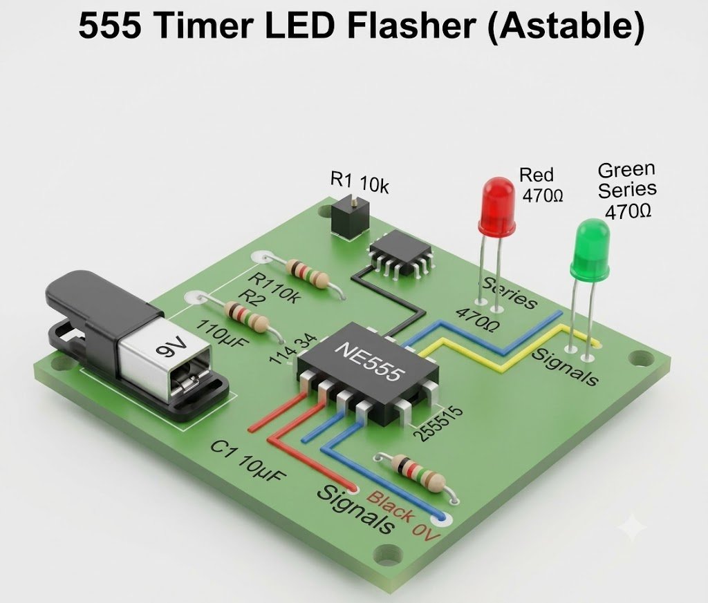
Target: about 1 Hz with a bright, visible flash. Choose C = 10 µF, R1 = 1 kΩ, R2 = 10 kΩ. Then f = 1.44 / ((1000 + 20000) × 0.00001) ≈ 6.9 Hz — too fast; scale C to 100 µF for 0.69 Hz, or accept ≈7 Hz as a lively strobe. We will build the 10 µF / ≈7 Hz version so the meter can measure it easily. Expected thigh ≈ 76 ms, tlow ≈ 69 ms.
| 555 Pin | Connection | Notes |
|---|---|---|
| 1 GND | Ground rail | — |
| 2 TRIG | Tied to pin 6 and capacitor + | Watch-dog of the lower threshold |
| 3 OUT | 220 Ω → LED anode; LED cathode to GND | Sources up to 200 mA |
| 4 RESET | To VCC | Tie high or the chip stays reset |
| 5 CTRL | 100 nF to GND | Noise immunity; do not skip |
| 6 THR | Capacitor +, and R2 to pin 7 | Upper threshold sense |
| 7 DISCH | R1 to VCC, R2 to pin 6 | Discharge switch |
| 8 VCC | 5–9 V | Up to 15 V on bipolar 555s |
Power Up and Measure
The LED should flash about seven times per second. Measure VCC, then put the meter on pin 6: you should see it wandering between roughly 1/3 and 2/3 of the supply. If you own an oscilloscope, pin 3 shows the square wave and pin 6 the capacitor’s sawtooth — the most instructive two traces in all of hobby electronics. Count flashes for ten seconds and compare with your calculated frequency; within 15% is normal with electrolytic tolerance (±20% capacitors are common).
Tuning the Flash
Double C to halve the speed; double both resistors for the same effect with lower current. Replace R2 with a 100 kΩ potentiometer for a variable-rate strobe. For long-period flashers (once per minute), use 1 MΩ resistors and a low-leakage film capacitor — electrolytics leak too much at that scale and the timing wanders.
Try It in the Circuit Simulator
Our Circuit Simulator includes a 555 component — place it with R1, R2 and C, run the simulation, and watch the output LED flash at the rate your own formula predicts. Sweep the resistor values there first; arriving at the breadboard with verified numbers is how professionals prototype.
Troubleshooting
- LED solid ON or OFF: pin 4 floating (tie to VCC), capacitor polarity reversed, or pins 2/6 not joined.
- Frequency wildly off: electrolytic tolerance — measure the capacitor if your meter has a capacitance range, or try a film cap for accuracy.
- Erratic flashing: missing 100 nF on pin 5 and no supply decoupling; add 100 µF across the rails too.
- Chip hot: output shorted to ground or VCC — the 555 is tough but not immortal; check the LED resistor is present.
Safety Notes
- Observe electrolytic polarity; reversed capacitors vent.
- Stay within the 555’s 15 V maximum supply, and add a series resistor to every LED.
- Do not drive relays or motors directly from pin 3 without a flyback diode and current check.
Conclusion
You designed an oscillator from a formula, built it, and measured reality matching the math — the complete engineering loop, with no microcontroller in sight. The 555’s thresholds and discharge pin reappear in monostable timers, PWM dimmers and tone generators; master the astable and the rest of the 555 catalog is free.